Small inverter relay diagram
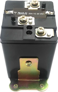
Stabilizer relay diagram (1st from top is NC then NO then Common, always check and refer the diagram in the relay for confirmation)
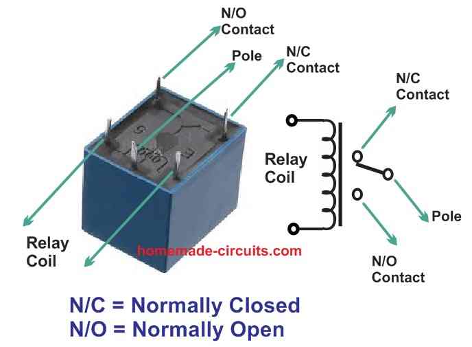
Working
So when the relay is off the pole or common is connected with normal close and when the relay is activated the pole/common is connected to normal open.
Relay checking process
- 🔍 Burn marks / smell burnt → Replace relay.
- 📏 Coil resistance 50Ω–1kΩ = OK, ∞ = Open, 0Ω = Short.
- 🔌 Apply coil voltage → Click sound = OK, No click = Faulty.
- 🔄 Contacts: COM–NC = continuity (no coil), open (with coil).
- 🔄 Contacts: COM–NO = open (no coil), continuity (with coil).
- 💡 Load test → If fails under load = Contacts burnt.